Typical Boat and Battery Wiring Schematic
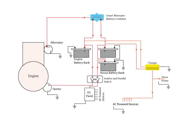
Here is a typical wiring schematic of how your batteries are connected to your boat and charging system.

The alternator produces electricity from the engine as it turns. The electricity is distributed through a device called a battery combiner. The battery combiner is a smart device that can charge multiple banks of batteries but still keep each bank separate and apart. Here, the house and engine bank remain electrically separate; current can not flow from one bank to the other but the alternator can distribute electricity to both at the same time.
After the Battery Combiner, the electricity flows to charge the batteries. Following the house bank set, electricity can then flow to the DC Panel where it is distributed to the boat’s DC electrical devices.
The isolator and parallel switch are manual switches that allow the boat user to disconnect the DC circuit from the batteries. This switch can also connect the house bank and engine bank together just in case energy is needed from one bank to the other. For example, if your engine bank was flat and you needed some energy from the house bank to start the engine.
Electricity also comes into the boat from the shore pedestal. It flows to the charger which converts the power to DC and then charges the batteries. Shore power can also power any AC devices on the boat.
The above is a very typical setup on a boat. The system gets a little more complicated when adding in solar and generators to be shown in a few pages.


